This post will focus on the creation of a detailed spur gear set in Adams View. A previous blog showed how to create a fixed mathematical representation of a gear set between two joints, but what if you want to see more detail relating to the gear interaction itself, like backlash? For this we will use the Adams Machinery package.
The first step will be to ensure that you’ve got points defined at your gear centers.
Once you’ve created your center points you can start the process of creating the gear pair by clicking on the gear icon in the Adams Machinery ribbon bar indicated below.

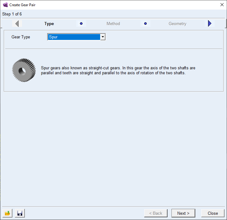
Once you’ve clicked the gear icon the Create Gear Pair interface will open. It will start you on Step 1 of 6, which is the gear type selection. Adams Machinery currently allows you to select from six different gear types to model:
- Spur Gear – Standard straight cut gears.
- Helical Gear – The gear teeth are no longer parallel to the axis of rotation. These gears are used if you have high forces, high speeds or if the gear noise needs to be low.
- Bevel Gear – These gears are used when the axes of your shafts are not aligned. The most common use is for shafts with a 90° offset, but almost any angle can be used.
- Worm Gear – Used for a large speed reduction where the shaft axes are crossed and do not intersect.
- Rack Gear – Converts rotational motion of a gear to the linear motion of the rack. The teeth can be straight or helical.
- Hypoid Gear – This is a quieter (and smoother) version of the Bevel Gear, where the pinion axis is offset from the center of the larger gear axis.
For this example we will use the Spur Gear option as shown in the image below.
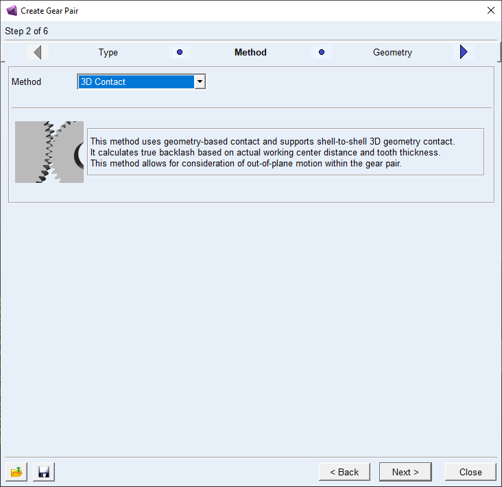
The next step is the Method step. Here we can decide in how much detail we want to model the gear pair. There are once again a couple of options to choose from:
- Coupler – This is the simplest method and is just a variation on the method that was used in the previous blog. For this method the forces between the gears are ignored and only speed reduction or multiplication is applied.
- Simplified – This method uses an analytical approach to calculate the gear forces and backlash. The use of analytical methods makes this a very fast solving method that could be used to efficiently model complete gearboxes.
- Detailed – This method uses the involute function and the specified contact properties to calculate the contact forces. This method can calculate the contact between up to three teeth at a time and is useful when friction between the gears needs to be considered.
- 3D Contact – This method uses geometry-based contact and calculates the actual backlash based on the working center distance and tooth thicknesses. Because the gear models are fully three dimensional out of plane motion can be allowed.
- Advanced 3D Contact – This method is an expansion on the 3D Contact method with the addition of gear tooth flexibility. For all the previous methods the gear teeth were modeled as rigids, but for this method the teeth are meshed and a separate Nastran based FEA is solved in the background. This process is completely automated and no additional FEA software is required. The disadvantage of this approach is longer solving times and the potential for very large temporary files for the FEA process (in the order of 1GB to 50GB files dependent on your mesh settings).
For our hand drill we will use the 3D contact method as shown below.
Once you’ve selected the contact method the next step is to define the geometry. The image below shows you the parameters that you need to define in order to model the gears. The first thing to take note of is that Gear1 is the driver gear and that Gear2 is the driven gear. The driven gear, or gear two can either be defined as an external gear, with the teeth on the outside, or as an internal gear where the teeth are on the inside.

Before defining the gear parameters, you can set the gear module (pitch diameter divided by the number of teeth) and pressure angle (measured in degrees) as well as the axis of rotation. Once you’ve done this you can define the gears themselves.
In order to define the gears you need to define the gear’s center location, number of teeth as well as the width of the gear. Optionally you can define the bore diameter as well (hole diameter).
You additionally can define some gear tooth parameters. Your first option is to choose if you want to define a standard or modified profile. For the standard profile you can define the profile shift coefficient, addendum and dedendum factor. The profile shift coefficient can either be positive or negative with a default value of 0. The addendum and dedendum factor is used to calculate the addendum and dedendum with the module as follows:
Addendum/Dedendum = Module * Addendum/Dedendum Factor
If you change the profile type to Modified you need to define the tooth thickness, addendum radius and dedendum radius. The tooth thickness is measured at the pitch circle and must be less than 10 times the value of the module.
Optionally you can also modify the gear teeth by defining the tip relief start, tip relief coefficient and crown magnitude.
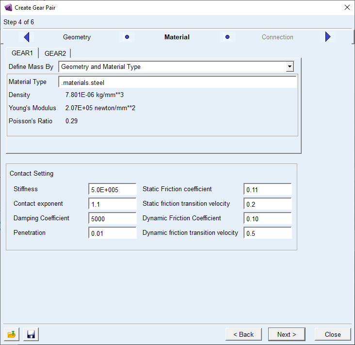
Once you’ve defined both your gears you can move on to the next step, which is the material definition and contact settings.
The material settings can be defined in the similar methods to other Adams parts. For the Contact Settings you can define various parameters. For more detail on the effect of each of these parameters please refer to the Adams View help documentation as well as the definition of the IMPACT function in Adams View.
The next step after defining the material and contact settings is to define how the gears are connected and to what they are connected. The options for connecting the gears to parts are as follows:
- Rotational – The gear is connected with a revolute joint.
- Compliant – An Adams bushing is used to connect the gear to the part.
- Fixed – The gear is connected using a fixed joint.
- None – With this option no connection is made. You can use this option if you want to add a joint later yourself, or if you want to define an Adams Machinery Bearing between the part and the gear.
Once you’ve done this you’ve created your gear pair.
If you look in your model tree in Adams View, you will notice that a new section was added, named Gear Systems. If you expand this section, you will see both your gears listed as well as your gear pair.

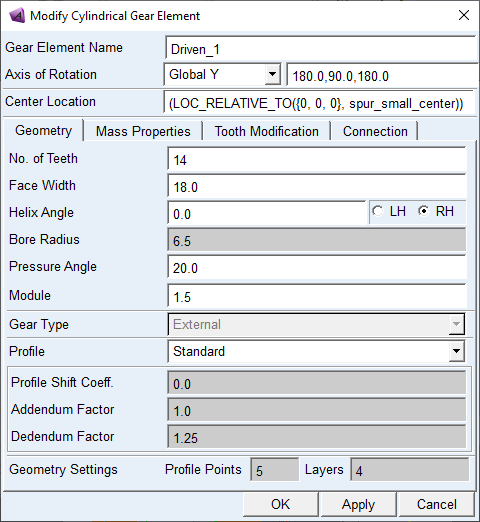
So, if you only want to modify one gear at a time you can do so by right clicking on the gear in the model tree and selecting modify. This will open a window different to the one that you used when creating the gear pair. In this window you can modify all the aspects of each gear separately, however if you want to return to the original interface where you created the gear, you can right click on the gear pair listed in the model tree. The only thing that you can do in the original creation interface that you can’t do in the separate gear modification interfaces is to change your contact type.
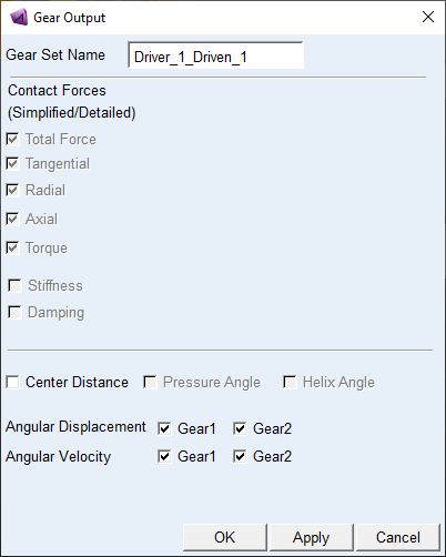
You can see what outputs will be available to you for your gear pair and possibly select some additional outputs based on your contact method by clicking on the Gear Output icon in the ribbon bar.

This will open the Gear Output window in which you can select your gear pair and then proceed to check or uncheck some outputs. Note that some outputs cannot be unselected.
Once you’ve solved your analysis you can plot the results of the gear interaction in the Adams Post Processor. The image below shows the angular velocity of the input gear in blue and the output gear in red. From this image you can see that there is clear backlash between the gears.

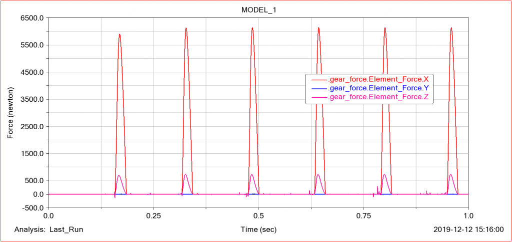
The contact force between the gears can also shown and in the image below you can clearly see the forces when the back of the gear teeth makes contact, indicating a bad gear set.