SIMTEQ Engineering has created a smooth-running procedure to assist clients with the complicated thermo-mechanical analysis requirement of the UIC510-5.
In short, the procedure based on the UIC510-5 requirements is as follows:
1. Thermal
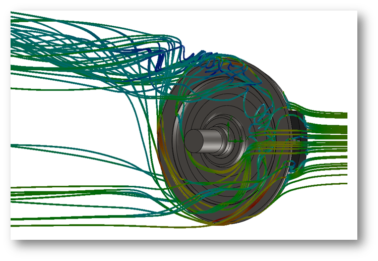
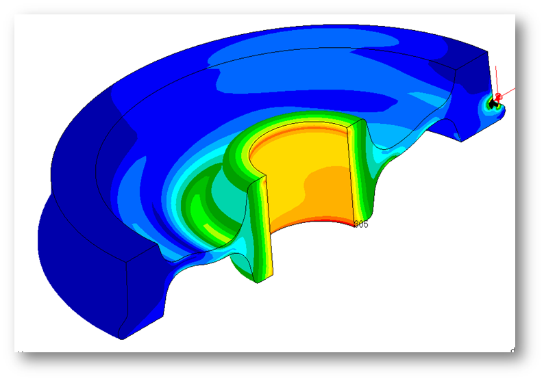
Analysis step 1: Heat input: The UIC specifies that the magnitude of the maximum braking energy that has to dissipate is 50 kW for 45 min at a running speed of 60 km/h based on a wheel diameter in the range of 1000 to 840 mm. Rig ventilation must be provided at the speed of va/2 (e.g., 0.5 x 60 km/h = 30 km/h) at a distance of 700 mm from the axle. A computational fluid dynamics (CFD) analysis is conducted of the rotating wheel with the heat input on the running surface and the simultaneous cooling air flow over the wheel at half the speed. The output from this analysis is mapped onto the pre-stressed FEA model to find the cumulative displacement and stresses in the wheel and axle. SIMTEQ Engineering uses scFlow for its ability to simulate the air flow around the complex bodies while adding the thermal load simultaneously. There is also no need for the user to build the required mesh since this is done automatically. scFlow, furthermore, has the ability to map the temperatures and pressures onto the finite element mesh (Nastran BDF) for export.
Analysis step 2: Cool down: The wheel should cool down until the thread temperature has dropped below 50°C. In the CFD analysis, the wheel is allowed to cool down, and the resulting temperatures of the complete wheel are then mapped again onto the FEA model to obtain the cumulative displacement and stresses in the wheel and axle. The same procedure as in step 2 is used to map the results to the FEA model.
2. Mechanical
Analysis step 3: Shrink fit: The wheelset should be shrunk onto the axle with the appropriate interference fit as proposed by manufacturers or as specified by the client (depending on the manufacturing process followed). The UIC 510-5 make use of a 0.325 mm mean compression over the diameter. A finite element analysis (FEA) is conducted to calculate the induced stresses due to the shrink fit. SIMTEQ Engineering prefers using MSC Marc for its superior ability to simulate the press fit with contact between the wheel and axle and the ability to add the temperature distributions calculated in the CFD analysis on top of it to obtain a true thermal-structural analysis result.
3. Thermo-Mechanical
Analysis step 4: The temperatures as calculated in steps 1 and 2 are mapped onto the FEM as thermal loads, and the resulting stresses in the wheel as a whole are then determined. These stresses are then combined with those from the press-fit analysis (step 3) to obtain the combined effect.
4. Mechanical
Analysis step 5: The UIC-510-5 specifies that three-point loads, as indicated below, should be applied to the wheel's running surface. The resulting stresses are again calculated using FEA and again combined with the stresses due to the initial press-fit step.

- Load case 1: Vertical loadcase, tangent track. In addition to the shrink fit, the specified vertical load is applied in the FEA model.
- Load case 2: Vertical and lateral load case. In addition to the shrink fit, the specified vertical and lateral loads are applied in the FEA model.
- Load case 3: Vertical and lateral load case, points and crossings. In addition to the shrink fit, the specified vertical and lateral loads are applied in the FEA model.
Analysis step 6: Haigh diagram: The post-processing of the FE data has to be done to provide information for a uniaxial fatigue analysis based on a Haigh diagram.

If you require a thermo-mechanical analysis, please contact us because we enjoy solving difficult problems!