In this article I will put a compelling argument forward why glued meshes (with a gap) are a much better option that the more traditional stitched mesh approach for modelling thin plate structures with 2D shell elements.

Stitched plates left vs. glued plates (with gap) right.
The Compromise
FEA analysts still often represent thin solid parts using 2D (shell) elements with a thickness property as an economical alternative to modelling the thin parts using actual solid elements, as shown in Figure 1 below, despite a number of known disadvantages.

Figure 1: Typical model where using shell elements are far more economical than solid elements.
When modelling a structure like the typical example shown above [Figure 1], it is quite clear that using solid elements to represent the plates, with at least 2 elements through the thickness, is not a feasible option (unless you require the additional detail for a specific reason, or you have lots of storage space and time on your hands).
One of the known disadvantages of shell element models though, which many analysts have knowingly lived with in favour of the computational advantage these models have over solid element models, is the fact that mathematically there exist duplicate material at T-junctions where such elements meet. In a typical T-joint as shown below [Figure 2], the surfaces are extended until they intersect to ensure a connection that allows load transfer between the elements, but it does not take into account that in reality the connection is on the surfaces of those thick sections.

Figure 2: Stitched (congruent) meshes with thickness property (rendered in 3D on the right)
Visually, such a mesh looks like the image above on the left with a proper connection, while mathematically, it represents what is shown on the right, with an effective material overlap in the T-junction area.
The glue sceptics
The above compromise was for a very long time an acceptable one since FEA has always been understood to be an approximation method. Glue contact, when used with the half thickness gap present, is now an even better and more reliable alternative to use, but traditional analysts are still quite sceptical about the glue contact approach, so lets compare these two.
Glue contact explained
In the glue contact approach, surfaces are not extended to connect physically and therefore retains a gap in the model as shown below [Figure 3] which eliminates any duplicate material, but using an automated approach, those elements are however mathematically connected through what we term "glue contact".

Figure 3: Glued (un-stitched) meshes with thickness property (rendered in 3D on the right). In MSC Apex the glued elements are rendered as such (on the left) in the pre-processing phase.
It is important to note that the thickness property dictates whether or not the elements should be connected and secondly, it determines how many elements over the width of the connection should be connected (compare the deformed shape of the bottom plates in the results further down in this study).
The glue sceptics explained
The sceptics have a number of reasons why not to use glue contact and why to continue using stitched meshes, despite the known disadvantages:
- "We have always done it this way" - A valid response since FEA analysts have build up credibility in their methods over the years by getting very accurate results with their FE models and even if not accurate, they have always been very useful to identify problem areas and evaluate alternative designs. Replacing a well established method with a new unfamiliar one takes away that built up confidence and experience. New methods require new experience and credibility to be developed.
- "Glue contact is difficult to set-up" - This was indeed the reality for some time, especially for large models with hundreds of bodies in contact which was a time consuming process and very error-prone.
- "Glue contact takes longer to check and fix than to create stitched meshes." - In many cases the burden to resolve glue contact through a trail-and-error process would take longer than it would to create a connected stitched mesh in the first place. The only way the analyst could check the contact was to submit an analysis and view the results, either looking at the contact status or for relative displacement between elements. Such a process could result in many iterations of changing settings and re-analysing specific load cases to resolve contact errors.
- "Glue contact adds computational load to the analysis" - In some case the computational burden to define glue contact may take longer than using stitched meshes.
Why consider glue contact?
While the arguments against glue contact is rapidly evaporating with recent advances in FE solver technology and user interface improvements, it should not be evaluated on these arguments alone. It should first be said that the traditional method of stitched meshing did not become the norm as opposed to the glue contact method, but in the absence of glue contact technology. Glue contact was only developed much later and until recently, was really difficult to get to work. You might even say that early attempts at introducing glue contact may have given it a bad reputation.
But the advantages that glue contact promised was incentive enough to justify its further development as shown in these pro-glue contact arguments:
- "Glue contact resolves the duplicate mass issue" - Since the surface meshes are no longer extended to meet, no duplicate material exist at a t-junction. Depending on the plate dimensions, this may or may not be significant as demonstrated further down in this study.
- "Glue contact can take the width of a contact patch into account to represent the connection stiffness more accurately" - connections of stitched meshes does not take the thickness (width) of the connection into account in terms of the force-bending transfer, thus resulting in longer force moment arms from the connections. Glue contact can represent the physics of the connection better by distributing the load transfer through all the elements in the thickness region.
- "Glue contact simplifies the mid-surface creation process since mid-surfaces do not need to be extended and stitched" - As desktop computing power became more powerful and accessible, many analysts started favouring meshing even thin plate structures with solid elements as opposed to using shell elements since the longer solving times of solid meshe, were often shorter than the time it would take to create a correctly stitched surface mesh and with far less effort involved. Glue contact eliminates the need to extend and stitch every surface, making the creation of mid-surfaces a very simple process with the glue taking care of the connections.
- "Un-stiched (but glued parts) can easily be re-positioned in a model" - making a slight modification to a stitched model is not a simple process and involves deleting parts and recreating them in a new location. Simply moving a rib in a stitched model into a new position is simply not quick or easy. Glue connections however simply need to update when a part is moved, providing total freedom to make quick structural changes.
- "Glue contact adds less computational time than the time required to created stitched meshes" Recent experience with glue technology is that there is little additional computational time involved. Once glue contact is defined (essentially the only part of the process that does consume time), the glue merely acts as additional constraints between the elements while having less degrees of freedom than a stitched mesh with additional elements to represent the connection.
- "Nodes between connecting parts does not need to tie-up". Usually the connecting parts are stitched to ensure that the nodes tie-up at the connection point, this can however cause heavily distorted elements at the connection point if there is a large difference in the element sizes between the connecting parts. Glue contact only requires the elements that needs to be glued to one another but the element sizes and node locations for the connecting parts does not need to be the same.
Comparing the different methods
In this demonstration (see Figure 4 below), the stiffnesses of different parts using different element types and mesh densities, but representing the same structure, were compared. The parts in Figure 4 were setup as follows:
- Parts 1 & 5 use glued shell element meshes (having a gap between the surfaces).
- Parts 2 & 6 use stitched shell element meshes (having duplicated mass in the overlap area.
- Parts 3 & 7 use solid Hex8 element meshes.
- Parts 4 & 8 use solid Tet10 element meshes.
The only difference between the top row of parts (1 to 4) and their corresponding bottom row parts (5 to 8) are their respective mesh densities. Parts 1 to 4 have higher mesh densities than parts 5 to 8.
As a benchmark, the shell element parts were compared to the solid meshes (which are traditionally considered to be the most accurate).
The reason different mesh sizes and solid element types were introduced in the benchmark was to also show the relative sensitivity of the results to such differences when comparing the results from the different shell meshes to these solid parts.

Figure 4: Comparing eight different meshes representing the same T-section. Parts 1 to 4 has double the mesh density of Parts 5 to 8.
For the stiffness comparison, a normal modes analysis was used since $latex w_{n}=\sqrt{k/m} $ with $latex w_{n}$ measured in [rad/s] which means that the natural frequency of the parts is directly and only affected by the stiffness and mass of the structure. Although we know that parts 2 and 6 in Figure 4 are slightly heavier due to the small portions of duplicate mass, the other parts are identical in weight and therefore any difference in natural frequency is a direct measure of difference in stiffness.
To quantify the influence of the mass difference (3.76%) on the natural frequencies of parts 2 and 6 compared to those of the others, assuming equal stiffness, the natural frequencies of parts 2 and 6 should be 1.83% lower than the others due to the additional mass alone based on our simple equation for natural frequencies.
Therefore, any difference in natural frequency of more or less than 1.83% between parts 2 as well as 6 and the rest of the parts, can only be attributed to a difference in stiffness since the the same material was defined for all the parts.
To emphasize the effect of the connection stiffness, the parts were constrained as follows: The top and left most edges of the T-sections were constrained while leaving one edge free on each (see Figure 5). The first and second mode shape results shown in figures 6 and 7 show the effect of the chosen constraints.

Figure 5: Constraint scheme for each part

Figure 6: Mode shape 1
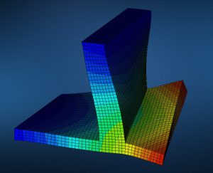
Figure 7: Mode shape 2
Before we compare the stitched versus glue results, Figure 8 shows the advantage that shell meshes have above solid meshes when comparing solving times (especially for the small element meshes).
Figure 8 shows a recording of the solution times of the various parts, normalised to the quickest running part, part 7 (the stitched coarser shell element mesh).

Figure 8: Solution time impact of the different meshing schemes
From the above solution time results it can be seen that the finer Tet10 element mesh took the longest to solve (almost 4 times longer) due to its large number of nodes and there was indeed a premium paid for the solution time of the glued parts versus the stitched parts, although only in the region of 2.9% (when comparing the solving times of Part 1 to Part 2 and Part 5 to Part 6).
The most important comparison however is below in Table 1 when comparing the actual results (in Hertz) between the different parts. These results show that the stitched meshes are far less stiff than the other meshes.

Table 1: Natural frequencies [Hz] calculated for the different meshing schemes
To put the differences between these values in perspective, here are the results in graph form with frequency along the bottom axis:

From the results shown in Table 1 the stitched meshes for both mesh densities under predict the natural frequencies by up to 20%, compared to the average solid mesh results, while the glued meshes predict the frequencies to within 0.7%. To put that in perspective, the impact of the glued meshes compared to the solid meshes, are less than the impact of the mesh densities between the same solid meshes alone!
Figure 9 shows the results of table 1 normalised to the average of the solid mesh results.

Figure 9: Stiffness impact of the various meshing schemes
From the above stiffness impact results it can be seen that the stitched models consistently under predicts the stiffness compared to the other meshes.
But why is the glued method so much more accurate than the stitched method?
The answer to this question can be illustrated using Figure 10 below.

Figure 10: Bending behavior of the glued meshes mimic that of the solid meshes.
The reason why the stiffness of the glued meshes are on par with that of the solid meshes are because the thicknesses of the connecting plates are taken into account in the "footprint" of the glue contact. In Figure 10, the bottom plate bending pattern of both the glued and solid meshes clearly shows the effect of the vertical plate's thickness.
When comparing that to the stitched mesh plate bending, the bottom plate's bending is not affected by the vertical plate's thickness and therefore is much less stiff (up to 20% less stiff in this comparison).
In conclusion
It is true that the shown error above between stitched meshes and glued meshes becomes less severe with larger plate length to thickness ratios but there is yet one other aspect to take into account: Model preparation time.
When solving a model with solid elements are not an option, creating a stitched mid-surface mesh is far more time consuming than a glued mid-surface mesh.
The reasons to support my claim that glued meshes are far better to use than stitched meshes, are:
- Glued meshes eliminates the duplicate mass issue at plate intersections
- Glued meshes provides an accurate representation of the intersection stiffness
- Creating a midsurface model from solids, for glued meshing, is a one-click operation (in MSC Apex)
- The validity of the glue contact can be visualised before attempting the analysis (in MSC Apex)
- Changing part positions in a glued model is much easier than in a stitched model
- Glued meshes retains the part hierarchy with a computational advantage in the new computational parts scheme of MSC Apex where parts in follow-up analyses are not re-computed if they did not change
In short, the only disadvantage glued meshes have over stitched meshes, is history!