Topology Optimization is the science of designing by volume mass and load which is a very powerful tool to have, but it has one significant flaw: If you neglect to account for any single significant load case (i.e. combination of loads and boundary conditions), you may be set up for disaster.
It is unfortunately this single fact that puts people off from using Topology Optimization since it is nearly impossible to dream up all the possible loads and combinations of loads, load magnitudes and directions that a part or structure may experience throughout its life. That is, if you don't bring in extra help.
Click the image below for an overview of the suggested design process:


Train bogie experiencing complex load combinations during its travel
In this blog I will show the importance of taking all possible load cases into account when using Topology Optimization and then show how to use Multi Body Dynamics software to get all the required loads and combinations of loads. As an example we will use a railway wagon bogie frame which could experience an unimaginable amount of different load cases during its life time.
But first we look at a simple example of a 4 leg garden table that is designed using Topology Optimization, with and without one significant load case omitted from the process: the twist load case which could represent a scenario where the table feet are stuck in the grass while someone tries to rotate the table.
The image shown here on the left is a typical steel garden table that we would like to design from scratch using topology optimization.
For our design, we assumed the part will only experience a number of different vertical load cases such as someone sitting on the table, standing in the middle of the table, the table being filled with dishes of food etc.
The chosen design domain (also called the material envelope – from which material can be taken away) looked like this:

Supplied table design domain (material envelope)
Note that when using Topology optimization, material can only be removed from what is provided here. No material can be added during or after the analysis, therefore it is important to start with as large as possible volume of material. If we anticipate that any cross members would be required, this initial material envelope should include it since the end result will not have any material outside of this design domain.
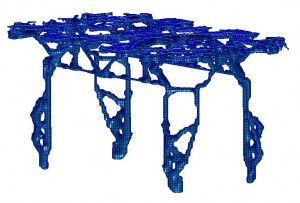
Then after supplying the various (vertical) load cases, the topology optimization result looked like this:

Result with significant load case neglected
The result is not yet a pleasing design but it does give us fair insight into where important structural members should be placed as well as their ideal shape and size.
Now remember, the rotate load case was not supplied in the optimization run.
When this rotate load case is now applied to the structure, we see a problem:

Stress hot spots identified under load case not included in design
The stress hotspots shows a particularly weak area on the table legs and it is quite obvious that the design shows low stiffness in rotation which could be a cause for concern.
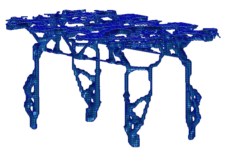
However, if we included the rotate load case to the optimization process in the first place, the design would have looked like this:
Result with 1 extra load case included
Again, this is far from a pleasing design but what it does show, is how dramatically the results are influenced by the provided load cases. It should also be remembered that the topology optimization process cannot add material where it was not given in the first place, therefor this is probably still a suboptimal design for the provided load cases, but valid under the set of conditions.
And the resulting stress plot for the rotating load looks like this (showing none of the previously high stress hotspots):

Insignificant stresses under previously neglected load case
Note that both table designs had the exact same mass targets, with the only difference being the one excluded load case in the first instance.
This clearly shows how important the choice of load cases is for topology optimization analyses and why people shy away from using it (because they are worried that they may exclude an important load case unknowingly). But there is a solution to this challenge.
As a side note, take note that this optimization example on the table is far from complete. For a complete analysis (to get a feasible end result) far more boundary condition options and load combinations should be included in the analysis. Furthermore, it might also be practical to exclude the upper level of elements to ensure a solid table top (if so desired). Regarding the chosen design domain (material envelope), it should be noted that when the end result includes boundary elements, it is a good indicator that a larger material domain is required for an even lighter or stiffer design.
Now what if we needed to design a much more complex structure, such as railway wagon bogie, which may see hundreds (if not thousands) of different load cases every day?
Enter Multi Body Dynamics (MBD) simulation software.

Image showing force input changes over time at various bogie attachment points
By using MBD software, true life like events can be simulated of the structure in operation from which we can simply extract all the significant load cases, without worry that we might exclude anything important. The only concern then becomes to ensure that at least all the possible events are covered.
In the next example, a train wagon travels through a section of sharp corners over a non-perfect track (with vertical and horizontal irregularities). This event induces all sorts of dynamic instantaneous loads on the structure that need to be designed for. The force time history plot above shows dramatically changing force magnitudes and resultant force directions on some of the bogie frame attachments points over time. Each point in time can be regarded as a load case which might need to be taken into account when utilizing topology optimization.

Rail vehicle with front and rear two-axle bogies
This particular bogie frame has 21 attachment points and looking at the force time histories at any of these locations, the complexity of the changes in force magnitudes are clear. None of these extracted load cases would even have been possible to foresee, yet alone be accurately included in a topology optimization run without MBD software.
One might now be inclined to think that each and every nanosecond’s forces now need to be included as a load case in the optimization process, fortunately that is not the case.

Curved and irregular track causes dynamic load changes on bogie frame
The following blog post Extracting loads for FEA from Multi Body Dynamics (MBD) Software, will show how to identify the most significant load cases from Adams, Adams Car or Vi-Rail and how to extracted them as load cases for use in a topology optimization run using Patran and MSC Nastran.
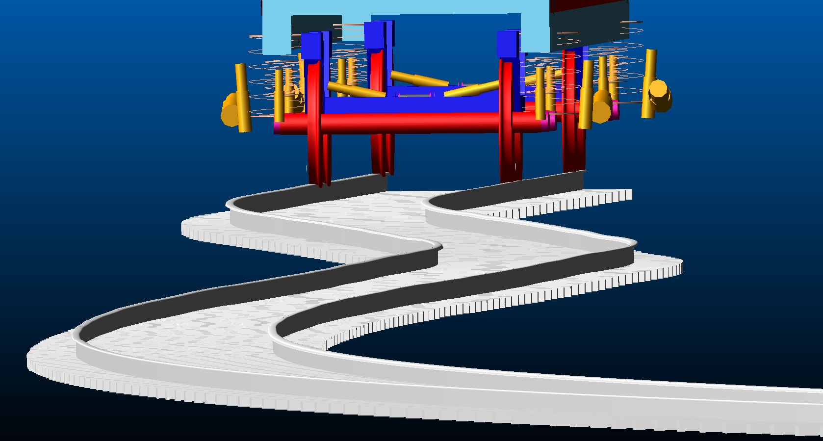
In that example, we start with a concept frame (on the left) and end with a final design based on the topology optimization design (on the right).
See From Concept to Design through Analysis for an overview of the ideal process below.

From concept to designed optimal structure
See also Numerical Optimization of Structures – An introduction for a more fundamental overview on optimization.